
As I have never been operational on the 6m band, the plan to build a dedicated antenna for that band came up. Due to my space restrictions, I chose this design by DK7ZB because, as he writes, “all you need is gain”.
Mechanical Construction
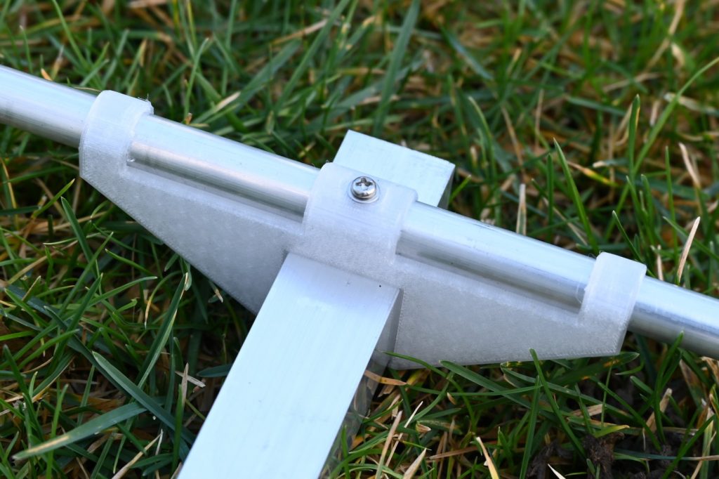
I used 25mm square aluminum tube as boom and all the elements are made from round aluminum tubes with 12mm diameter. As I did not find the right gear for that dimensions from the shops I typically use, everything was newly designed and 3D-printed as already shown in another article on the 144MHz Yagi-Uda antenna. The element holders were designed to go around the boom in order to offer some stability even without any screws. The screw through the element then adds the last bit of stability to keep the elements in place. Finally, the mast fixture was assembled from some parts from the local hardware shop.
Electrical Construction
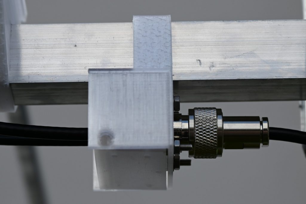
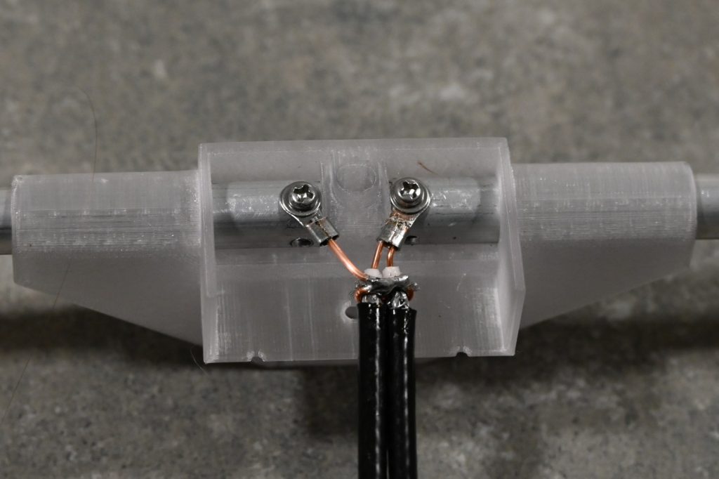
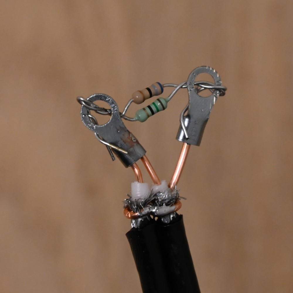
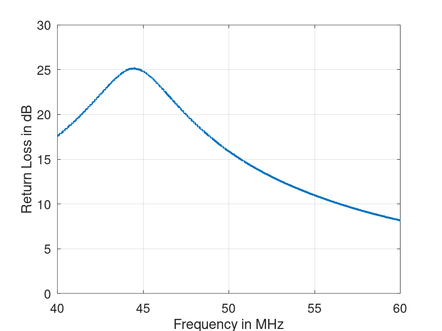
The antenna itself was designed with a feed impedance of 12.5Ohm and can be matched to 50Ohm using a quarter wave transformer with 25Ohm. This can easily be built with two parallel 50Ohm cables. The procedure itself is straight forward: Put a connector on one end of the two 50Ohm lines, a resistor with 12.5Ohm at the other end and adjust the length of the lines until you reached the lowest return loss at the desired frequency which is around 50MHz in this case. As for my other projects, the actual length required for the lines is way below the expected length using the wavelength and velocity factor. In the graph below, the return loss of the matching section is shown with the length about right according to frequency and velocity factor. Unfortunately, I forgot to save the final match at 50MHz.
Putting it all Together
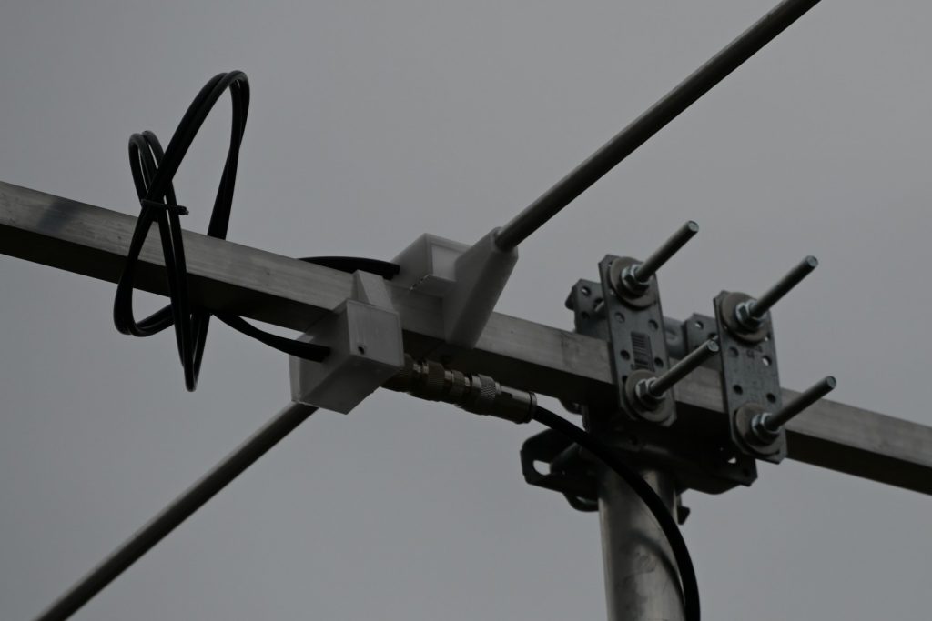
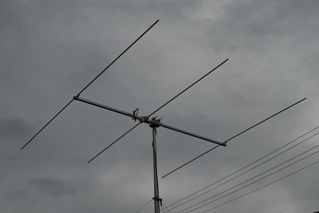
After putting the mechanics together with the matching network and mounting it on a mast, the optical result looks quite impressive in my small yard.
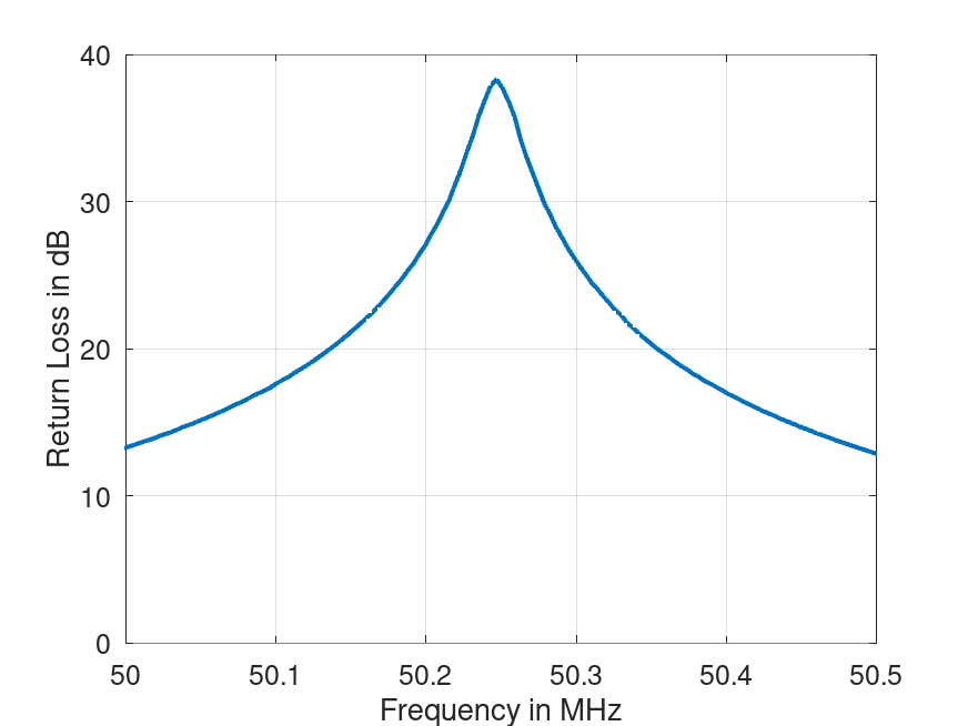
The resulting return loss is as expected very narrow and at a higher frequency as in the original design. This was expected to some degree because I used 12mm elements without 16mm inner parts as described by DK7ZB. According to EZNEC I should have ended at 50.28MHz which would be good for digital modes and SSB operation. As can be seen from the graph below, the maximum return loss of 38dB sits at 50.25MHz. From the graph one can read the 20dB bandwidth as 210kHz (from 50.14MHz to 50.35MHz) and the 13dB bandwidth to be 490kHz (from 50.0MHz to 50.49MHz) which is quite perfect for me.
After some first trials, the results look promising but I am looking forward to real operation with this antenna while the conditions improve towards the summer.